Forewords
I write this book in order to share knowledge on various computer science related topics that I have found myself interested in. I have always prevented my self to write as my fear of not writing content good enough took a hold on it. Hopefully the content of this book, and the experience you have by reading it, will let you discover new knowledge while enjoying it.
Furthermore, I would like to thank my family and friends for all the support they have given thorough my life.
Finally I would like to thank the most influencing teachers I had during my university days, those are the people that led me to the work I have today, and changed my life for the better:
- Professor Nicolas Gaud, for making me discover computer science and GNU/Linux.
- Professor Frederic Lassabe, for supervising me and teaching me Networking and Cybersecurity
- Professor Nicolas Lacaille, for showing me the ways of embedded systems
- Professor Michel Briand, for giving me passion for physics and electromagnetism
- Professor Frédéric Holweck, for opening my eyes on mathematics and that no, it doesn’t have to be painful
- Professor Corinne Mirabel, for teaching me human/soft skills and how to communicate and share with others
- Professor François Spies, for showing me the ways of the research world and hands-on skills of development
- Professor Hsu Fu-Hau, for encouraging me to follow my dreams and teach me about Cybersecurity
Author: Vincent CHAPUIS 沙文森
Chapter 0 - Foundations
Computer science is the study of problem-solving. This necessitates method and precision.
Problem solving can be seen as the process of taking an information input (problem statement), and produce a result, output (solution to the problem).
The machines called computers are for us an interface that lets us automate this process.
Part 1 - Computer Architecture
A computer is an electrical device, a machine, that can be programmed to accept data input, apply operations to those data and give a result output. It can also display those results to the one using it (user) as well as store them in a physical media.
The operations that are applied are defined in advance in the form of instructions known as software, while being executed on a set of physical devices called hardware.
Software (also referenced as program or application) is a set of instructions that orders the computer to execute given tasks in order to obtain a desired result.
Hence a computer will, execute tasks that it was given by a software creator (developer/programmer/software engineer) given physical resources it has access to, letting it solve a far higher number of tasks compared to a human given a same amount of time. This can then be helpful to any kind of application domain like for: artists, students, business, etc… The only limits being the capacity of the hardware and the imagination of the person who is writing the program.
Examples of programs:
- Microsoft Windows (Operating System (OS), which is a special kind of software that runs other software)
- Power Point (Presentation program, software to display information as a slide show)
- Excel (Spreadsheet, application to store, organize and analyze data in tabular form)
- Firefox (Web Browser, application for accessing websites)
- Pac-Man (Video Game, entertainment application)
We know now that a computer is made of 2 things:
- Software
- Hardware
Which could be compared to a piano (hardware) and the music (software).
Both the hardware and the software of a computer are made of several parts that works together to accomplish the given tasks. Like an orchestra, where each instrument has a specific role to play in the overall music.
Section 1 - Hardware
We will now talk about the different physical components of the Computer, its hardware.
Principal Components
- Processor (Central Processing Unit, CPU), which is the “brain” of the computer, it executes software instructions and make complex calculations.
- Random-access memory (RAM, role: main memory of primary storage), fast electronic memory used to temporary store data and instructions to process.
- Read-only memory (ROM), permanent electronic memory used to store software that does not need to be changed often, this kind of software is also known as firmware. In the specific case of consumer grade computers, this software is known as the BIOS (old) or UEFI (new), which is the first software that is loaded when the computer is turned on.
- Mass Storage device (role: secondary storage), various type of media used to store information on the long term (persistent data). Usually slower than the RAM but can for a similar cost, store a vastly superior amount of data.
- Hard Disk Drive (HDD), electro-mechanical data storage device that uses magnetic rotating physical disks to store information. Slower than alternatives, but also cheaper.
- Solid-State Drive (SSD), data storage device without moving parts, only made of electronic circuits. Usually faster and less sensitive to physical damage than the HDD.
- Video Card (also known as graphics card or GPU), component used to generate a feed of graphics output to a display device.
- Power Supply (PSU), is the component that supplies electricity to the rest of the components, which is the necessary source of energy for all of them to work. Usually a power supply will convert the AC power from the wall outlet to DC power which is the common kind of electrical power used in electronics.
- Motherboard, central component of the computer, board which connects all the other components together.
Peripherals
Peripherals are auxiliary devices used to transfer information in and out of a computer.
Hence there is 2 kinds of peripherals:
- Input device
- Mouse, hand-held pointing device
- Keyboard, typing device
- Microphone, sound recording device
- Webcam, video recording device
- …
- Output device
Of course some devices also have those 2 capabilities at the same time:
- External storage device
- Network devices
- …
Section 2 - Software
This section will go over the different kind of programs that can be found in a computer, its software.
- Firmware, low-level hardware control. In typical computers, the first software that is loaded and run during a startup (booting) is a special firmware called BIOS or UEFI (its successor). This software roles is to initialize the hardware and give hand to the operating-system.
- System Software
- Operating system, essential software that manages the entire resources of a computer and let the user interact with it. It also provides a platform to run application software. Examples: Microsoft Windows, Linux, MacOS, Android, …
- …
- Application Software, software that uses the computer system to perform actions that a user initiated. Examples: Microsoft office, Libre office, Adobe Photoshop, Steam, …
Part 2 - Digital Concepts
Analog vs Digital
Section 1 - Boolean Logic
Section 2 - Binary and Hexadecimal
Part 3 - Algorithms
Chapter 1 - Programming
Part 1 - Terminology and Principles
Part 2 - Writing Programs
Chapter E - Electronics
I would like to thank Robert Feranec and Phil Salmony for the content they provide online which is the main base of my electronics knowledge.
Part 1 - System Requirements
When starting a new electronics project, the first step is to define the system capabilities.
These requirements are derived from specific stakeholder needs, whether they are personal, coming from market research, etc…
TL;DR (“too long; didn’t read”)
To start your project you need to define:
- System Description
- 1st Level Requirements Breakdown
- High Level System Block Diagram
- 2nd Level Requirements Breakdown
- Detailed Technical Requirements
- Detailed System Block Diagram
System Description
The System Description serves as the project’s foundation.
In order to define it, identify the following:
-
Functional Intent
“What specific tasks or operations this system needs to perform?”
-
Purpose
“What is the objective or problem this system needs to solve?”
-
Operational Context
“In what environment and for what specific application will this system be used?”
Write down the answer to those questions, consolidate the answers in a formal format and you will end up with your System Description.
Example:
An autonomous, high-speed maze-solving robot designed to navigate a $16 \times 16$ grid, map the environment, and execute the fastest possible path to the center.
This will guide the next design steps.
Requirements Breakdown
After the System Description finalized, decompose the system into several technical specifications.
For example:
- Sensing
- Utilization of high-speed Infrared (IR) emitter-receiver pairs to detect wall proximity and alignment without physical contact.
- Locomotion
- High-RPM brushed or brushless DC motors with high-resolution magnetic encoders for precise sub-millimeter positioning.
- Processing
- Implementation of a “Flood-Fill” or similar pathfinding algorithm to solve the maze in real-time while maintaining high-speed stability.
- Connectivity
- Removable Wireless Telemetry for testing
- Power Source
- Battery powered
System Block Diagram
Draw a high-level diagram representing the different system components as well as their signal and power connections.
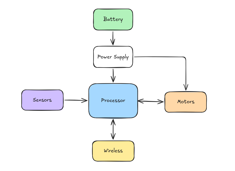 System Block Diagram Example
Detailed Design Specifications
Go through each high-level requirements and break them down further in smaller engineering targets.
Connectivity
When having connectivity requirements like USB or other communication channels, try to determine through educated guess and calculations the necessary bandwidth of data you will need for your application based on other requirements (sensor poll rate and sensor data size, etc…) in order to better determine what will be the bandwidth requirements for your communication channel.
Example:
If your application need sampling like ADC measurement. Use the Nyquist Frequency to determine the sampling frequency requirement. Hence the sampling rate should be at least twice as fast as the frequency of interest. https://en.wikipedia.org/wiki/Nyquist_frequency. To reduce quantisation error and get accurate reading ADC should have a bit depth from 8 to 24 bits, for example 12 is correct. Given your ADC bit depth and your sampling rate you can calculate your data rate: Single channel data-rate: 1 Channel x 12 bits x 40,000 samples per second = 0.46Mbit/s
Example:
- USB
- USB type: 1/2/3 (depends on your data bandwidth need, USB2.0 FS(Full Speed) is up to 12 Mbit/s and HS(High Speed) up to 480Mbit/s)
- Host/Device or Both (On-The-Go OTG)
- Connector: A/B/Mini/Micro/C
- Wireless chip
- Removable -> dev board with connector? (example: ESP-Hosted on ESPx board (Seeed Studio XIAO ESP32-C6), Custom cyw43 board )
- WiFi/Bluetooth
Note:
// TODO: improve this section
Do not forget to add ESD protection to all your connectors headers. ESD can easily damage your components.
Debugging Interace
// TODO: improve
- SWD(Serial Wire Debug) or JTAG(Joint Test Action Group)
Processor
- Brand
- STM32 is recommended
- Number of cores
- Clock speed
- Depends on necessary processing power
- Peripherals
- List down the requirements
- USB, SPI, CAN, …
- Packaging
- Avoid BGA and QFN to reduce cost
- Programming
- Debugging
- SWD(Serial Wire Debug) or JTAG(Joint Test Action Group)
Power Management
Source
USB
When using USB you will need to select the power delivery you need for your circuit. USB-C can negotiate the power it can deliver.
Input power from USB power rail is very noisy. needs adequate filtering. It has nominal +5V but can drop as low as 4.5V. Needs to watch out for regulator drop-out voltages. Can get to 500mA max current if negotiated with host. 150mA otherwise.
Battery
- Cell Type
- Primary (Non-Rechargeable)
- Secondary (Rechargeable)
- Cell Chemistry
- Lithium Ion (Li-Ion)
- 4.2V Charge
- 3.6V Nominal
- 2.5V End-Of-Discharge
- Most Energy Dense
- Most Volatile (Subject to thermal runaway, dendrite growth)
- Lithium Iron Phosphate (LiFePO4)
- 3.65V Charge
- 3.2V Nominal
- 2.0V End-Of-Discharge
- Less Energy Dense
- Less Volatile, hense safer (Not subject to thermal runaway neither dendrite growth)
- Nickel Metal Hydride (NIHM)
- 1.5V Charge
- 1.3-1.2V Nominal
- 1.0V End-Of-Discharge
- Usually used to replace AA (Alkaline non rechargeable)
- Lithium Ion (Li-Ion)
- Cell shape
- Cylindrical
- Better output current
- Sizes: 18650, 21700, 26650
- CID/PTC protection
- Prismatic
- Size: 103450, but usually custom and very large
- Pouch
- Lighter
- No standard size, but flat and usually smaller
- Subject to swelling (they will swell to 20% during their life)
- Cannot tolerate Physical abuse
- Cylindrical
- Number of cells (1S, 2S, …)
- Discharge rate/C-Rate
- Connector type
- Bare Cell (not recommended if you dont have a good protection circuit)
- JST-XH/SYP (3A rating)
- XT30 (higher current rating 30A)
- Cells topology
- Series (more voltage)
- Parallel (more current)
- Tested Batteries with certification
- Do you need to charge the battery? -> need charging circuit/IC
- Example: BQ24109 + 3V3 Buck Boost
- Battery Safety/Protection circuit
- It can come integrated with the battery pack (Pouch or Cylindrical), and is recommended
- Needed on the PCB if use bare cells with cell holder. Not recommended.
- Placed just after the battery connection (before the load/charger)
- Protects the battery from the load/charger
- Safety features
- Over Voltage Protection (OVP)
- Protects the battery from being charged past the peak charge voltage
- Under Voltage Protection (UVP)
- Protects teh battery from being depleted past the End-Of-Discharge voltage
- Over Current In-Discharge (OCD)
- Prevents the load from drawing too much discharge current
- Over Current In-Charge (OCC)
- Prvents the charger from providing too much charge current
- Over Temperature Protection (OTP)
- Cuts off battery output when the temperature is too high
- Short Circuit
- Cuts off battery output during a short on the battery output
- Over Voltage Protection (OVP)
- Example
- “Non Smart” IC, hardcoded protection values
- 1 cell R5480K261CL
- 2 cells R5460M208AF
- “Non Smart” IC, hardcoded protection values
Regulation
- Need different ones?
- Switching/Linear
- Digital: switching supply (buck converter) for efficiency. Digital is more tolerant of noise. Simple digital circuitry draws 100s of mAs.
- Analogue: Linear (LDO) regulators for improved noise reduction if the analogue circuit is for sensing. Analogue sensing circuitry usually draws less current than digital (10s of mAs).
Mechanical Requirement
- PCB dimension constraints (//TODO:)
- Mounting holes (grounded?)
- Connector placement
- Which case are we designing for? (conductor?)
Peripherals Requirements
- LED to indicate power on
- LEDs connected to MCU for status information
Other requirements
- Timing (crystal frequencies, types, etc..)
- ESD protection and filtering for EMC
Detailed System Block Diagram
Combine all previous requirements to draw a detailed system block diagram.
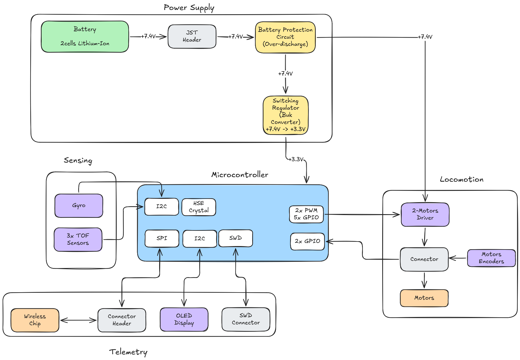 Detailed System Block Diagram Example
Part 2 - Sourcing
Once you have your system requirements, you will need to select which components to use in your system.
Selection Order
- Choose the main parts first, all the Main ICs
- Processor
- Motor driver
- Motors
- Screen
- Wireless Chip
- Sensors
- Any other important IC
- Calculate the power requirements (voltages and currents) of all previous ICs
- Choose power supply based on calculated power requirements
- Take in account continuous and peak currents at given input and output voltages
- Choose passive components (usually given in datasheets and application notes of ICs)
- Resistors
- Capacitors
- Op-Amps
- Any other circuitry that surrounds the main ICs
- Choose specific connectors
Selection Criteria
- Parts that are already in stock
- Low lead times
- Sufficient stocks
- Parts available at your PCB manufacturer (for example: JLCPCB)
- Parts you are familiar with
- Parts Distributor search (for example: Mouser or Digikey)
- Easy to assemble packages
- Don’t choose very small packages like 0201 or BGA, this will make debugging and soldering harder
- Right performance
- Least amount of additional circuitry needed
- Cost
- Part Lifetime
- Don’t take NRND (Not recommended for new design) parts
Distributor Parts Search
To seach for parts in a distributor like mouser.com:
- Select the product category (example:
Products > Semiconductors > Embedded Processors & Controllers) - Select the product type (example:
Microcontrollers - MCU) - Set first filters (example:
Manufacturer > STMicroelectronics,Mounting Style > SMD/SMT) - Apply (this reduce the possibilities of filters for each step)
- Set second filters (example:
Package/Case > LQFP-100 to LQFP-62,Data Bus Width > 32bit,Maximum Clock Frequency > 48 to 72Mhz,Program Memory Size > 64kB - 128kB,Data RAM Size > 20kB - 768kB) - Apply (repeat as many times as necessary)
- Sort by price. It is cost effective
- Tick
In StockandNormally Stocked. Ensure the parts are in stock. - Make sure the price is reasonable for the part you are searching for. (example: 2.55 USD per unit is reasonable for an inexpensive MCU)
- Check the Datasheet of the component and whether a footprint (PCB and 3D) is provided
Part Selection Examples
Microcontroller
Important Microcontroller (MCU) parameters:
- Programming tools, development environment
- Bus width (8 bit, 32 bit)
- Maximum clock speed (8Mhz to 550Mhz)
- Flash and RAM sizes
- Number of cores (typically 1), DMA, supply voltage
- Peripherals and I/O count (I2C, SPI, USB, CAN, Timers, GPIO)
- Packaging (BGA, QFN, LQFP) and package size
- Cost
You can have a preferred MCU type, for example STM32 are cheap, easy and have affordable programming tools, free IDE, good app notes and datasheets. They exist om various flavors:
- High-performance: F2, F4, F7, H7
- Mainstream: F0, F1, F3, G0, G4
- Low-power: L*
- Wireless: WL, WB
// TODO: change to another STM32 example that matches the macromouse example Example of a choice of MCU: STM32F103CBT6
- Very common MCU, LQFP-48 package, +3V3 supply
- Supports USB 2.0 FS natively and SPI
- Flash: 128 kBytes, RAM: 20 kBytes
- 72 MHz clock frequency
Power Supply
Check the Voltage and Current requirements
Many different types of DC/DC converters
- Switching (buck, boost, buck-boost, flyback)
- High efficiency, higher powers, switching noise, higher part count, harder layout
- Linear, low-dropout
- low efficiency, typically lower noise
General rule:
- Use switchers for digital circuitry
- Digital has high noise margins, higher current requirements Use linear regulators for analogue circuitry
- Analogue circuitry far more sensitive, lower current requirements
Switching Regulator
For the digital circuitry power supply
- Require step-down/buck switching converter
- Input voltage (+7.5V) is greater than output voltage (+3V3)
- Current requirements: TODO
Remember: higher switching frequency means smaller components around regulator, which is good (filters components can have a smaller value and thus a smaller size)
You can select parts with extra features: over-current protection, soft start-up, thermal shutdown, small SOT package, …
Passive components
Chapter E - Embedded Systems
I would like to give most of the credits to professor Nicolas Lacaille, who has been the best Embedded System teacher I have known and taught me all I know on embedded systems to this day.
What are embedded systems?
Embedded Systems are specialized computer systems with specific characteristics:
- Small in size
- Low power
- Efficient usage of PCB space
- Mostly uses microcontrollers (also known as MCU for microcontroller unit)
- MCUs are
- Small CPUs with many support device built into the chip
- Either low power for specific applications, or high performance in multiple applications
- MCUs are
- Typically interact with physical elements and often have real-time computing constraints
How to select a microcontroller?
To have your software application fulfilling the goals you set it to do, you first need to select the correct hardware that will enable the software to run and achieve its goals.
The selection criteria you need to think about when selecting a microcontroller for your application are:
- Power Consumption
- Peripherals
- Performances
- Price
After you chose your MCU, you either need to build your own PCB for your development or purchase an existing development/evaluation board. And you always need to make sure you can Flash and Debug your MCU with the given PCB.
Embedded development
Software tools
In order to develop the software you want to run on your embedded system, you will need a set of specific tools.
Cross (platform) toolchain
As a mean to translate your code into the target’s MCU, you will need to have a cross-compiler as well as a cross-linker for your desired programming language. C and C++ are the most commonly used embedded programming languages nowadays as they are very close to the underlying hardware and memory layout. However, given the recent interest to cybersecurity and developer’s convenience, the Rust programming language is gaining interest in the area (Resources for embedded Rust: the book - List of tools).
Simulator
In order to test your application before sending it to the real hardware, one can use a simulator or emulator.
QEMU
QEMU is an free and open-source (FOSS) generic emulator and virtualizer.
This course will not go through the usage of QEMU os it is a too broad of a topic, however if you would like to know more about it, feel free to check those resources: QEMU documentation - Rust program emulation with QEMU.
Wokwi
Wokwi is a paid simulator for a limited number of embedded development boards.
Flash tools
For your code to be transferred into the target’s MCU, you will need a flash tool. This tools transfers the program’s binary into the on-board memory of the MCU.
Debugger
When running programs on the target platform, you might want to inspect and control the execution of the program you are running in order to detect and correct bugs. Some tools called debugger, let you run step by step, stop the program at specific lines of code called breakpoints, or check and modify variable values at runtime.
To debug an MCU you will need a toolkit that lets remotely debug a chip, some well known toolkit in Rust are:
- OpenOCD + GNU Project Debugger (GDB). This is the most known kit and is mainly used for C application development.
- Probe-rs. A new player in the game, made in Rust and for Rust, aims to increase simplicity and ease of integration.
For your debugger to connect to the remote chip, you will also need a hardware probe. Most common probe protocols are JTAG and SWG, and commonly used probes are: ST-Link, J-Link, CMSIS-DAP.
Integrated Development Environment (IDE)
To develop our software application we will need an IDE to write code, as well as to interact with the debugger for convenience (it is also possible to use it from the terminal, but setting break points visually and having the executed line highlighted is speeding up things quite a lot).
For this purpose you can use any IDE that integrates with the debugger of your choice. Some good IDEs:
- Visual Studio Code (the VsCodium version is open-source and telemetry-less)
- VIM (or NeoVIM)
- Emacs
- Helix
Compilation
Compilation is the process to convert your source code into machine readable language that will be executed by the target processor.
To learn more about compilation there is tons of resources out there, I have made the choice not to go deeper into the subject and instead give summarized diagrams because as we know, a picture is worth a thousand words (and I am terribly lazy and do not have the time to talk about this topic in detail).
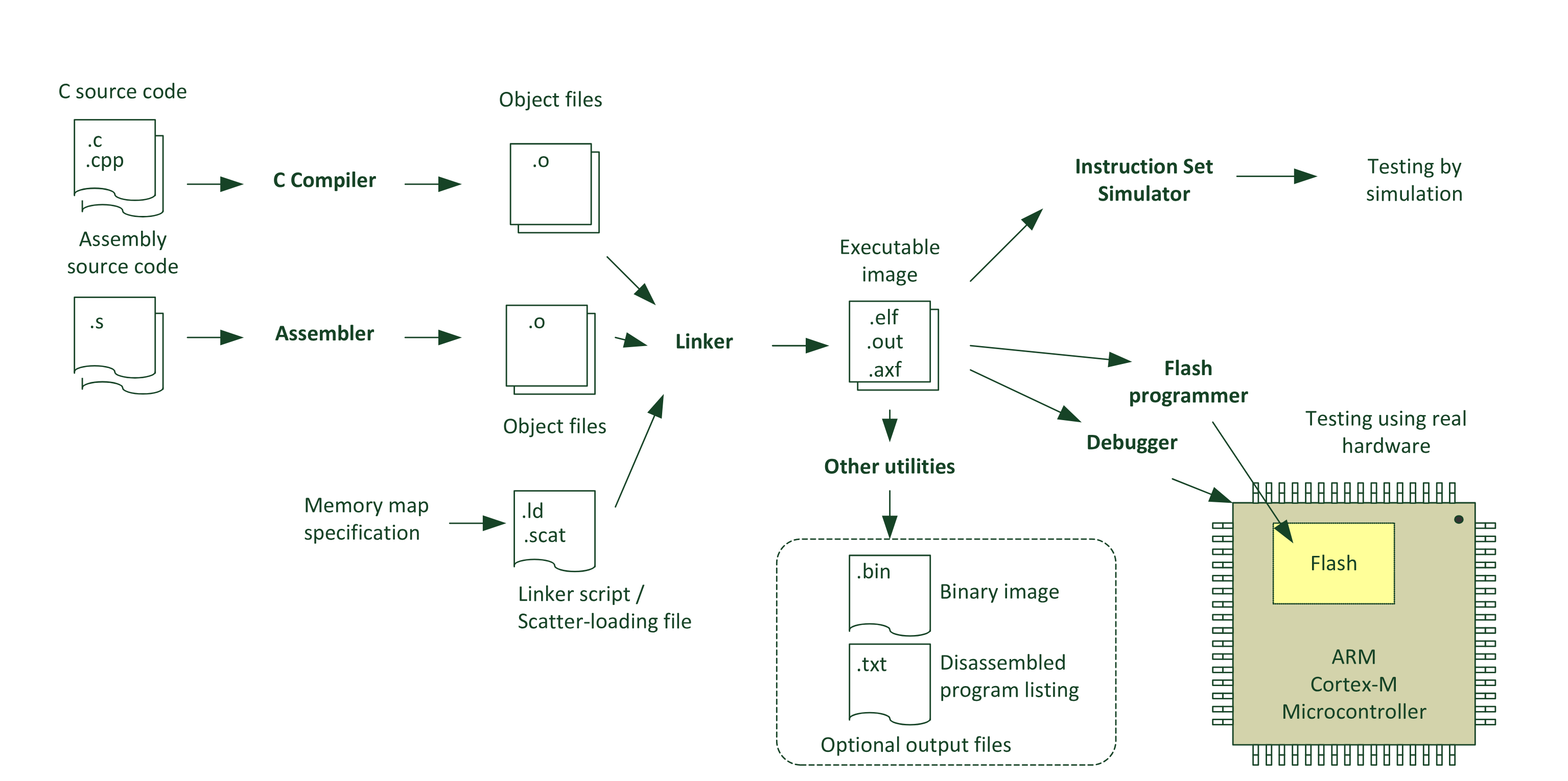 Common Compilation flow - The Definitive Guide to ARM Cortex -M3 and Cortex -M4 Processors
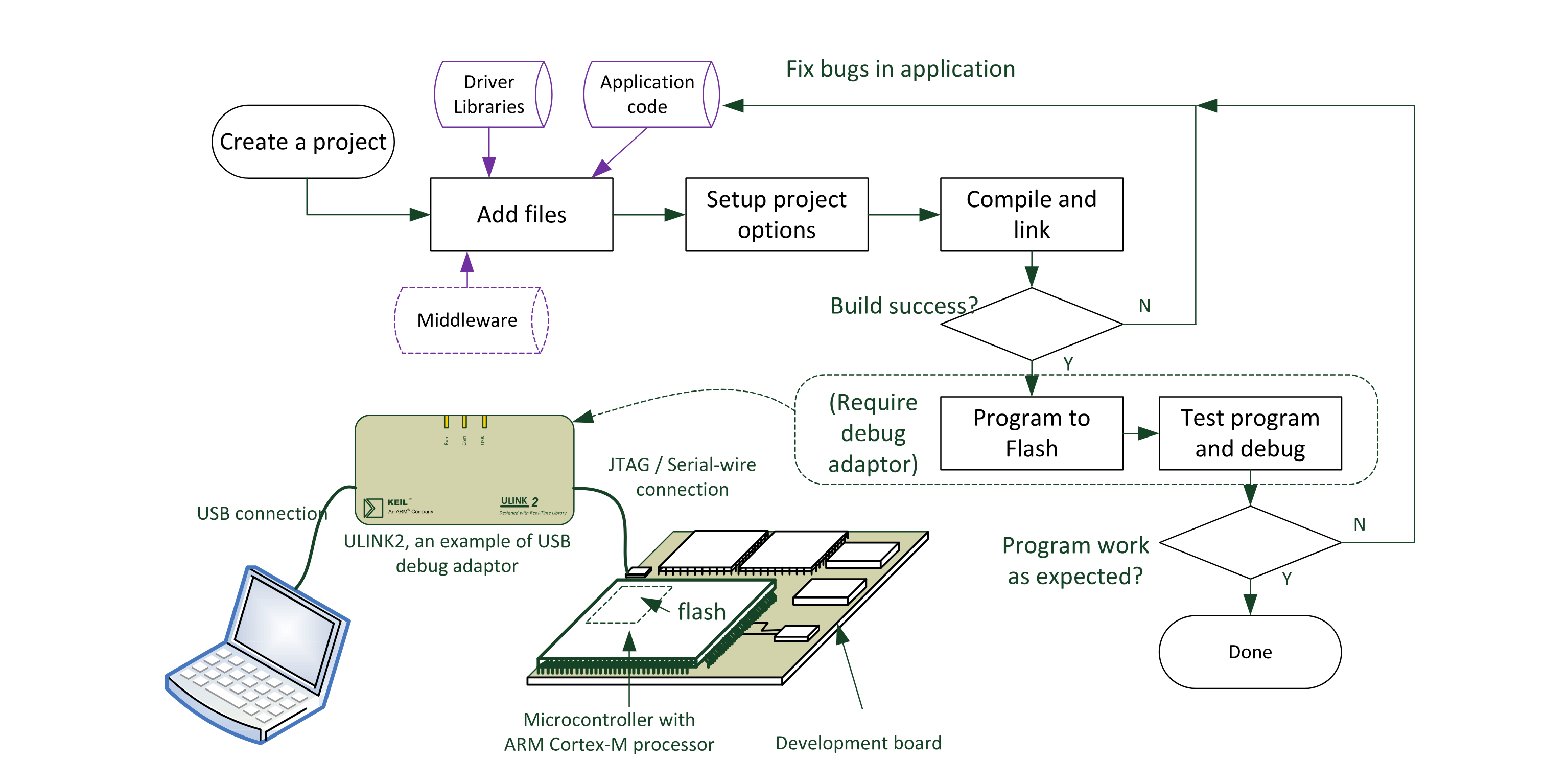 Embedded Software Development Flow - The Definitive Guide to ARM Cortex -M3 and Cortex -M4 Processors
Additional resources
There is lots of available resources online to complete the knowledge necessary in this domain and for specific application. Here is a non-exhaustive list of useful resources you might need on your embedded-system journey:
- ST Application Notes (AN) for STM32 development. (Example: AN2867 for oscillator choice).
- Analog Devices courses
- More Analog Devices courses
- List of Analog Devices courses
Part 1 - Memory
Part 2 - Peripherals
Peripherals
A microcontroller is a processor on a silicon designed with additional peripherals that communicates together through a System and Peripheral Bus.
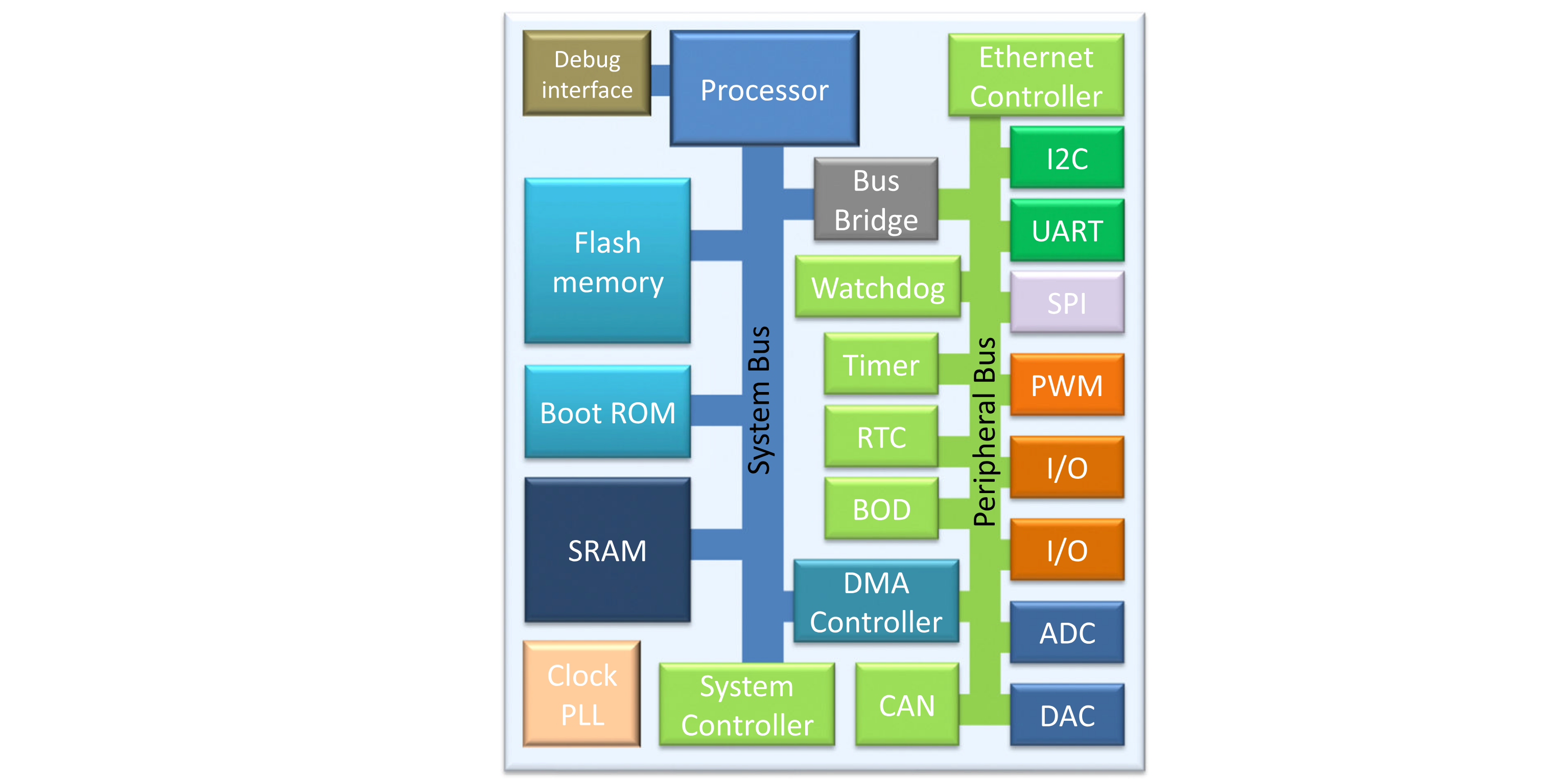 Microcontroller Architecture - The Definitive Guide to ARM Cortex -M3 and Cortex -M4 Processors
Configuration and setup
Peripherals are specialized electronic components that are configured and used through memory mapped register (address). Those peripheral configuration and register are provided by the microcontroller manufacturer in the MCU’s datasheet.
Memory Mapped Registers
(Thorough this course we will be referencing the datasheet and reference manual of the STM32L412KB MCU and the Nucleo-L412KB board. You can find them on the st.com website, and directly at these links: stm32l412kb_datasheet.pdf, stm32l412kb_reference_manual.pdf)
| Global Memory Mapping | Precise Register Boundaries |
|---|---|
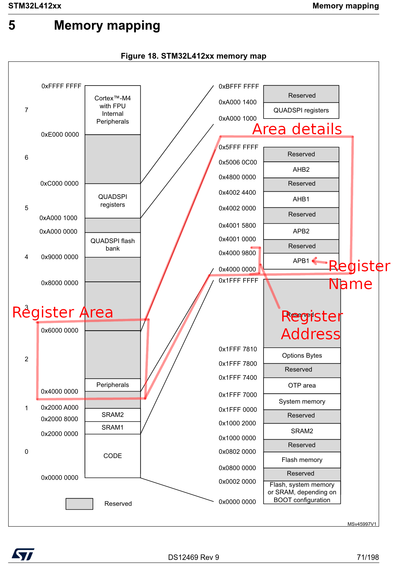 | 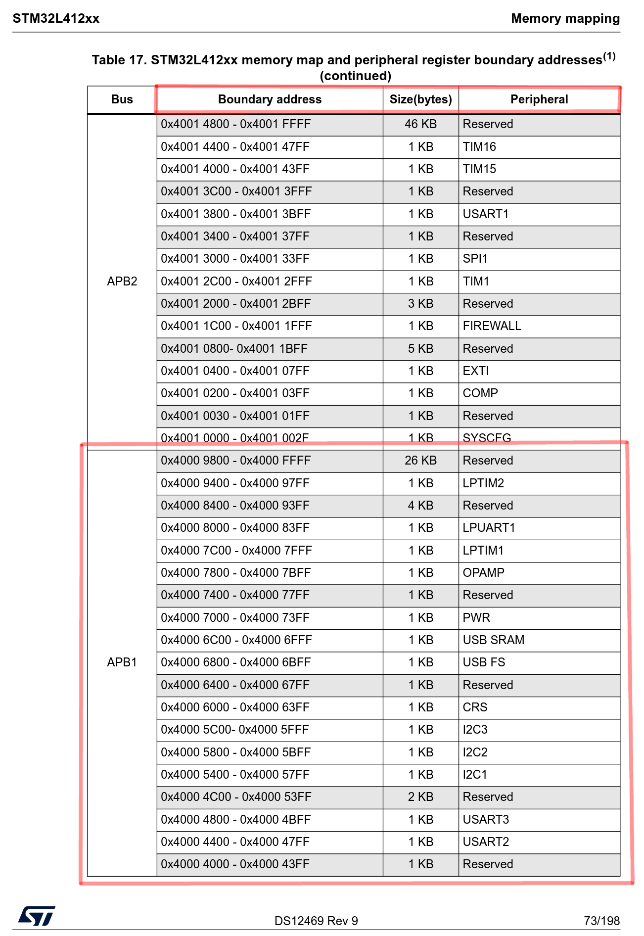 |
As we can see, for this MCU, the Peripherals registers start in the memory area of 0x4000_0000 and for specifically the Peripheral called I2C1 (which means its the first peripheral of type I2C on this chip, we will see more about this in the I2C chapter) at the address 0x4000_5400 and ends at 0x4000_57FF in the APB1 Bus/Register.
Alternate Functions
Some peripherals are accessible through alternate functions of GPIO pin (cf GPIO chapter).
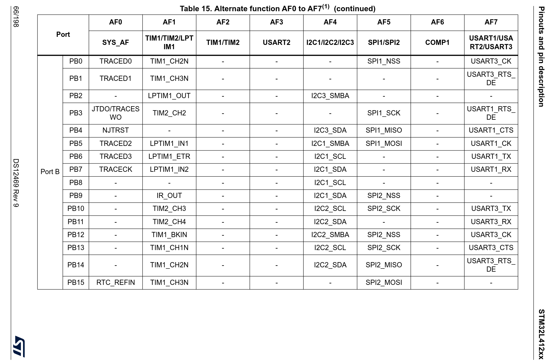 Alternate function list of Port B GPIOs - stm32l412kb datasheet
In this page, lets take an example with the pin PB0 of the Port B. By reading the table we are able to know that this pin can be configured in order to be either TRACED0 as part of the SYS_AF (System Alternate Function), either TIM1_CH2N (for “Timer 1 Chanel 2”) of the Tim1(Timer 1)/Tim2(Timer 2) peripherals, either SPI1_NSS (NSS component of the SPI protocol that we will see in another chapter) of SPI1/SPI2 peripherals, either USART3_CK of peripheral USART1/USART2/USART3.
So what does it mean? It means that for 1 physical pin, we can, through the firmware configuration, select from multiple possible function for that pin. It can have only 1 function at a time and different pins can point to the same function (however always configure only 1 function to 1 pin).
Each peripheral in the list we discussed above might need several different functions in order to operate, hence you will have to configure pins with different functions corresponding to the same peripheral name. As an example that we will detail later, in order to operate a SPI peripheral, you will need to configure for SPIx (where x is your SPI peripheral number) the functions SPIx_NSS, SPIx_SCK, SPIx_MISO and SPIx_MOSI.
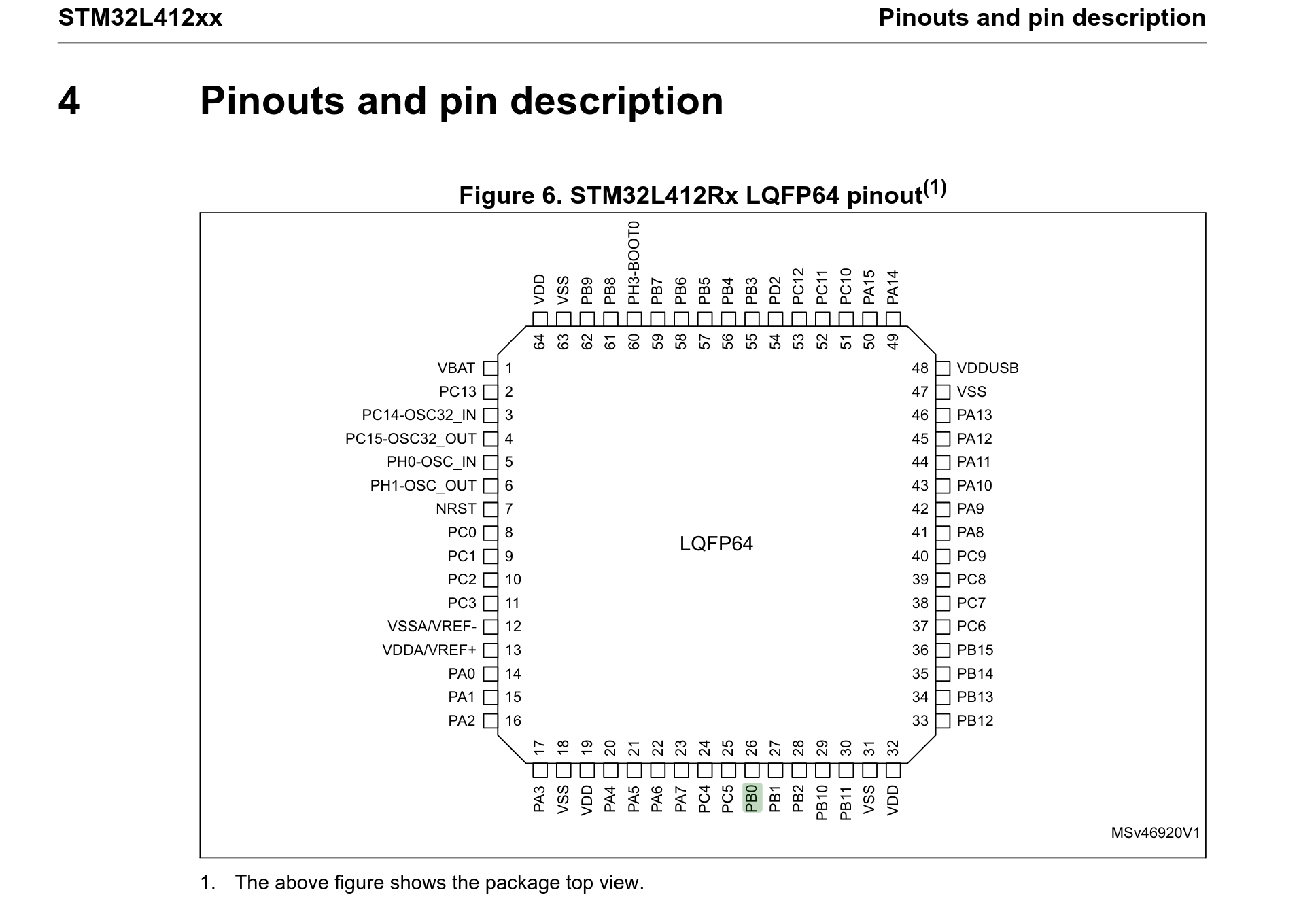
As for what “is” a pin? Its actually one of the many little metal leg that is coming out of your chip. For instance, for the STM32L412KB in its LQFP64 package (the package of a chip is the type of packaging/form it comes in, like the physical layout, shape and size of it), the PB0 pin we were talking about is located here, on leg 26: